Electrical Features
Insulation
The windings of the stators are made with enamelled copper wire (insulation class “H” – 200°C) with modified polyester resins and polyamide resin coating. The impregnation treatment, that is carried out during the manufacture, uses class “F” resin and provides high protection against electrical and mechanical stresses. As a result the winding is solid, without air pockets and with high heat transfer efficiency. The other materials used for standard production of our windings, are class “F” insulation but, upon request, we can provide windings insulated class “H” only.
Voltage frequency
In order to perform correctly, the voltage should not vary over a 5% from the rated value. When the motor is running respecting the above margin, the over temperature can increase other 10° C. Normal windings are suitable for voltages of 230 and 400 V and frequency of 50 Hz. Upon request, we can also provide motors for different voltage and frequency.
DUTY TYPES FOR ELECTRIC MOTORS
When the customer place an order, he shall declare the duty type. These are the most common standardized duties:
CODE: S1
NAME: Continuous running duty
DESCRIPTION: Once started, the motor works at a constant load at least until thermal equilibrium is reached. Ten that motor may be operated for an unlimited period.
TYPICAL APPLICATIONS: Hydraulic pumps, fans, blowers.
ABBREVIATION & EXAMPLES: S1
CODICE: S2
NAME: Short-time duty
DESCRIPTION: Once started, the motor works at a constant load for a limited period and thermal equilibrium is not reached. Motor will be started a second time then when its temperature has decreased to room temperature (starting conditions are restored).
Typical applications: Household appliances like eggbeaters, hairdryer and so on.
TYPICAL APPLICATIONS: Household appliances like eggbeaters, hairdryer and so on.
ABBREVIATION & EXAMPLES: S2 + duration of the duty | S2 30 min
CODICE: S3
NAME: Intermittent periodic duty
DESCRIPTION: A sequence of identical duty cycles, made up with a time of operation at constant load and a time at rest. When at rest, the motor is not fed. Starting current does not signifcantly influence temperature rise.
TYPICAL APPLICATIONS: Lifing motors.
ABBREVIATION & EXAMPLES: S3 25 %
CODICE: S6
NAME: Continuous-operation periodic duty
DESCRIPTION: A sequence of identical duty cycles, made up with a time of operation at constant load and a time of operation at no-load. When at rest, the motor is fed.
TYPICAL APPLICATIONS: Saw machines for wood, oil pressure pumps.
ABBREVIATION & EXAMPLES: S6 + cyclic duration factor* | S6 40 %
* Unless otherwise specified, the duration of a duty cycle for codes S3 and S6 shall be 10 min and the cyclic duration factor shall be one of the following values: 15 %, 25 %, 40 %, 60 %. The purchaser can anyway describe a special duty which is not standardized, according to the real duty of the motor. Where the purchaser does not declare a duty, we shall assume that duty type S1 (continuous running duty) applies. Duty types S2, S3 and S6 share a time to rest (no external load is applied) during which the motor lowers its temperature, thus affording to overload such motor with respect to the same motor when loaded with a S1 duty cycle. Moreover motors with duty types different from S1 are not included in high efficiency European regulation. So choosing the right duty means obtaining a motor that fully meets the requirements of the application where it will be installed, avoiding to get an oversized motor thus saving money. Further information can be found in IEC 60034-1 standard. If you have doubts, our technical department will be pleased to help you.
MOTOR CONNECTION DIAGRAM
The sense of rotation is referred to the motor seen from the shaft side.
The terminal block is seen keeping the shaft of the motor to its left.
Single-phase motors (with electronic capacitor)
The winding consists of 2 phases (Za e Zb), with a run capacitor (Zc) and an electronic capacitor (Zs). These 4 items have 2 ends each: A1, A2 for Za, B1, B2 for Zb, C1, C2 for Zc, S1, S2 for Zs. The nameplate voltage has to be supplied between A1 and A2.
Clock wise rotation
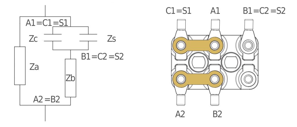
Anti Clock wise rotation
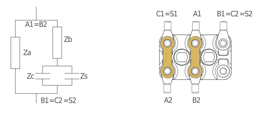
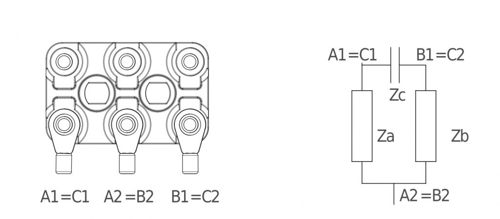
Two-phase motors
The winding consists of 2 phases (Za and Zb) with a capacitor (Zc). These 3 items have 2 ends each: A1, A2 for Za, B1, B2 for Zb, C1, C2 for Zc. The connection between A2 and B2 is made within the motor. The nameplate voltage has to be supplied between A2 and B1 or between A2 and A1 if you want to reverse the sense of rotation.
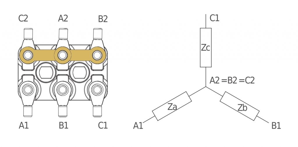
Single speed – three phase motors
The winding consists of 3 phases (Za, Zb e Zc). These 3 items have 2 ends each: A1, A2 for Za, B1, B2 for Zb, C1, C2 for Zc. The nameplate voltage shall be supplied between A1,B1 and C1. To reverse the sense of rotation of both speeds you have to reverse the position of any 2 supply cables.
Wie connection
High voltage on name plate
Delta connection
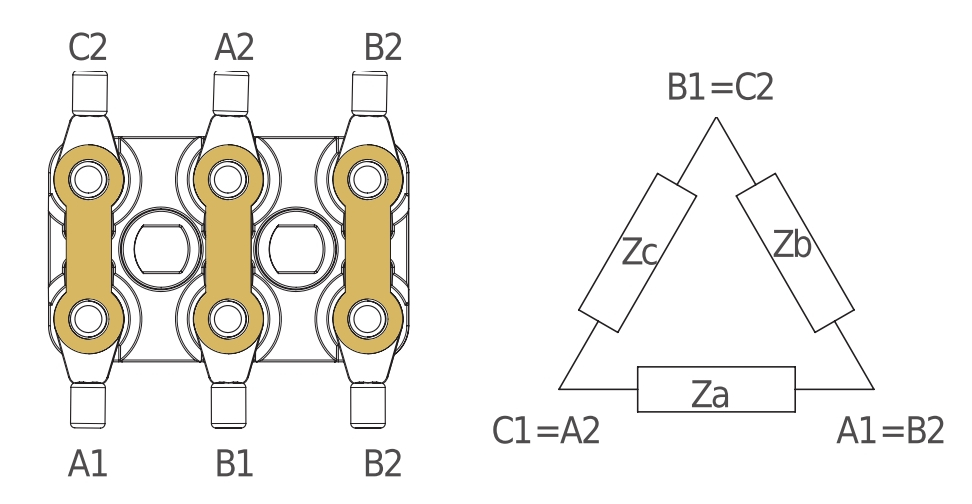
Low voltage on name plate.
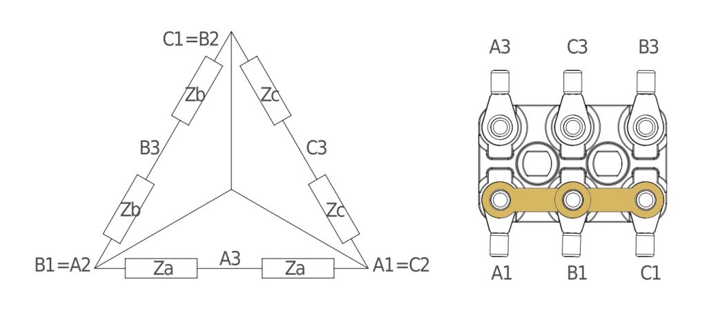
Two speed ∆/YY, single winding
The winding consists of 3 phases (Za, Zb e Zc). These 3 items have 2 ends each and 1 intermediate derivation: A1, A2, A3 for Za, B1, B2, B3 for Zb, C1, C2,C3 for Zc. To reverse the sense of rotation of both speeds you have to reverse the position of any 2 supply cables. In order to keep the sense of rotation of the motor in both speeds you have to translate the supply cables between A1=C2, B1=A2, C1=B2 and A3, B3, C3 avoiding to invert them.
Low speed
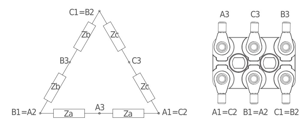
The nameplate voltage shall be supplied between A1=C2, B1=A2 and C1=B2.
High speed
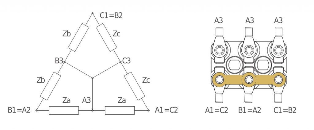
The nameplate voltage shall be supplied between A3, B3 and C3.
Two speed Y/YY, single winding
The winding consists of 3 phases (Za, Zb e Zc). These 3 items have 2 ends each and 1 intermediate derivation: A1, A2, A3 for Za, B1, B2, B3 for Zb, C1, C2,C3 for Zc. To reverse the sense of rotation of both speeds you have to reverse the position of any 2 supply cables. In order to keep the sense of rotation of the motor in both speeds you have to translate the supply cables between A1, B1, C1 and A3, B3, C3 avoiding to invert them.
Low speed
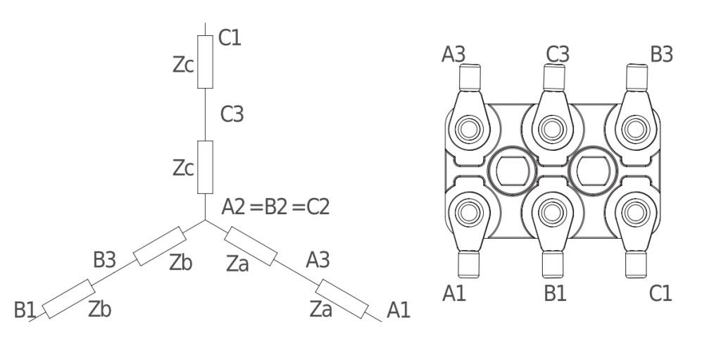
The nameplate voltage shall be supplied between A1, B1 and C1.
High speed
The nameplate voltage shall be supplied between A3, B3 and C3.
Two speed, double winding – three phase motors
The motor consists of 2 windings. Low speed winding consists of 3 phases (Za, Zb e Zc). These 3 items have 2 ends each: 3 of these terminals (one for each phase) are interconnected within the motor, for this reason you find 3 terminals, one for each phase: A for Za, B for Zb, C for Zc. High speed winding consists of 3 phases (Zd, Ze e Zf). These 3 items have 2 ends each: 3 of these terminals (one
for each phase) are interconnected within the motor, for this reason you find 3 terminals, one for each phase: D for Zd, E for Ze, F for Zf. The 6 terminals of the 2 windings must not be connected to each other in any case. In order to keep the sense of rotation of the motor in both speeds you have to translate the supply cables between A, B, C and D, E, F avoiding to invert them. To reverse the sense of rotation of one speed you have to reverse the position of any 2 supply cables.
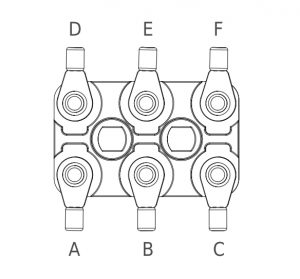
The nameplate voltage has to be supplied between A,B and C in case of low speed.
The nameplate voltage has to be supplied between D, E and F in case of high speed.
Three speed – three phase motors
The motor consists of 2 windings. The winding that provides high and medium speed is two speed n/2n or n/6, single winding type. The winding that provides low speed is single speed type.
These motors are supplied already wired, without terminal box.
2 cables come out of the motor: one with 7 contacts numbered, 1-6 connected to the Dahlander winding, the 7th for grounding, one with 4 contacts, 3 connected to the three-phase single speed winding, one for grounding. For the diagrams of two windings, see the previous cards.
Summing up:
to get high speed you have to supply 4,5,6 and short-circuit contacts 1,2,3 of the cable with 7 contacts to get the medium speed you have to supply 1,2,3 and hold open contacts 4,5,6 of the cable with 7 contacts to get the low speed you have to supply the three contacts of the cable with 4 contacts. In order to keep the sense of rotation of the motor in both high speeds you have to translate the supply cables between 1,2,3 and 4,5,6 avoiding to invert them. To reverse the sense of rotation of each speed you have to reverse the position of any 2 supply cables. You cannot choose between star and delta connection in the three-phase single speed winding.
DRATING AND PERFORMANCE OF SERIES MOTORS
ELMOR® motors are bench tested to ensure the rating and performance according to the IEC EN 60034-1:2010-02. The rated output applies for continuous operation within a max. ambient of 40°C and for an operational altitude of up to 1000m above seal level. In different working conditions, the specifications change according to the coefficients shown in the following graph.
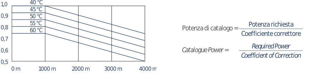
Temperature correction coefficient
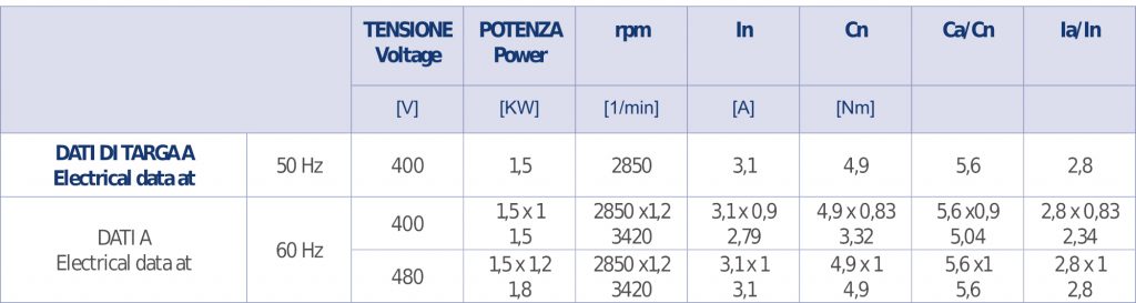
In the following table these symbols are used:
Ia/In=Starting Current/Rated Current
Ca/Cn=Starting Torque/Rated Torque
The ELMOR® motors are involved in an evolving program of bench testing, in order to improve their performance. As a result of this program, every technical data may change without need of MORATTO Srl to give notice of that.
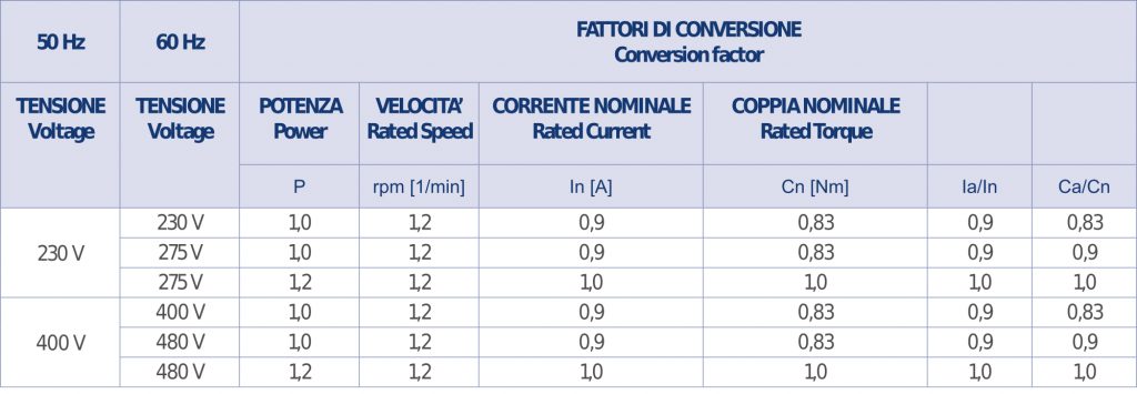
VOLTAGE AND FREQUENCY
ELMOR® motors can even run at 60Hz: voltage and rated output vary according the following table. Upon request, we can realize windings for special voltage and frequency.
Example of applications (approximate values)